Your Layout diagram of cmos inverter images are ready. Layout diagram of cmos inverter are a topic that is being searched for and liked by netizens now. You can Download the Layout diagram of cmos inverter files here. Find and Download all free photos and vectors.
If you’re looking for layout diagram of cmos inverter images information connected with to the layout diagram of cmos inverter interest, you have pay a visit to the right blog. Our site frequently provides you with suggestions for viewing the highest quality video and image content, please kindly search and locate more enlightening video content and graphics that fit your interests.
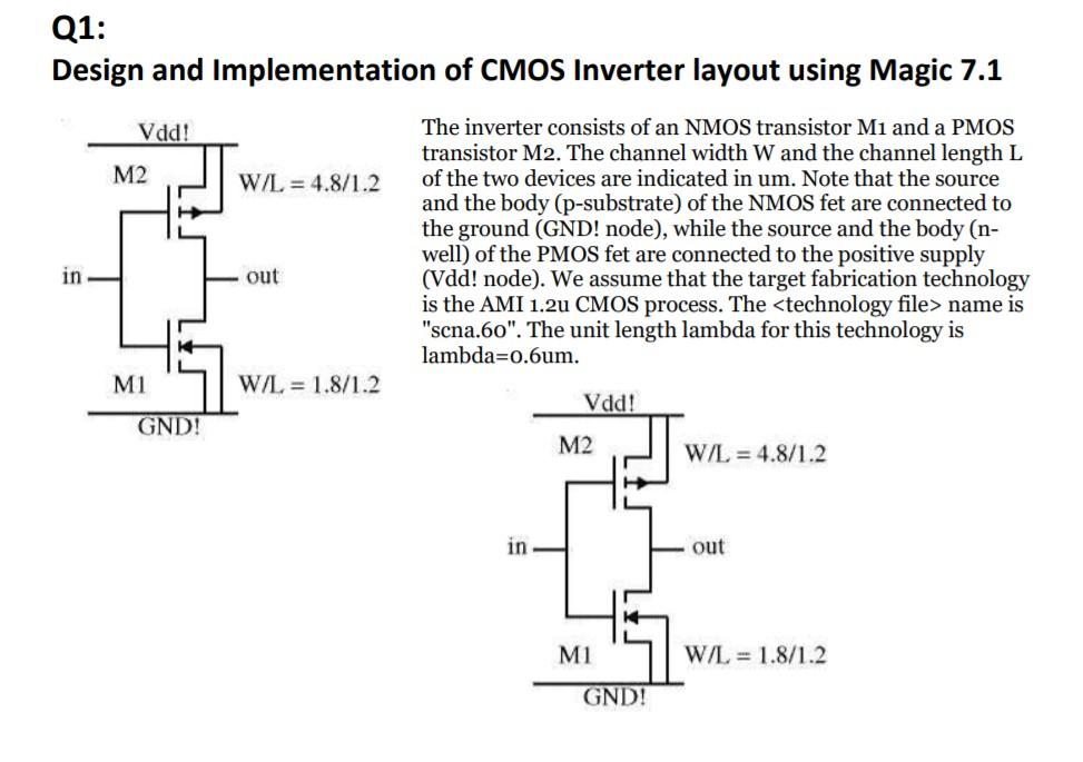
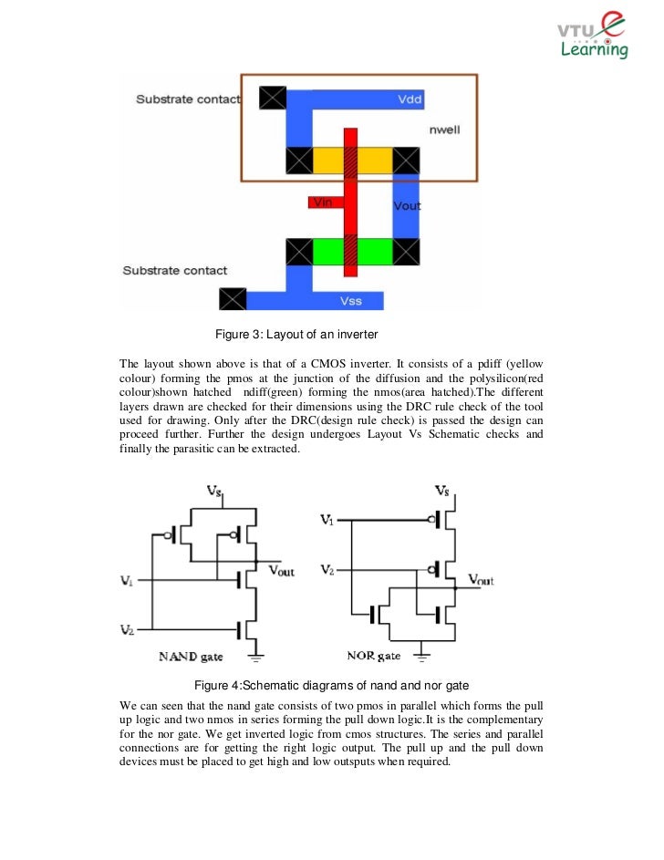
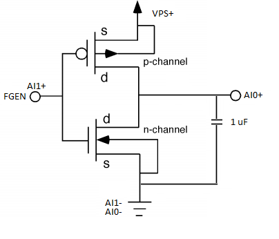
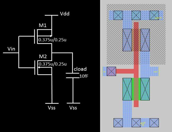
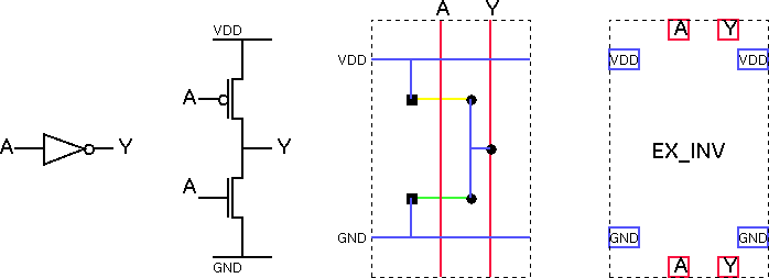
Layout Diagram Of Cmos Inverter. Subsystem Design Layout. Once the operation of an inverter circuit is carefully understood the results can be extended to the design of the logic gates and complex circuits. VLSI - Switch Logic. Figure below shows the circuit diagram of CMOS inverter.
 Schematic Diagram And Layout Of And Or Invert Aoi Gate Youtube From youtube.com
Note that to land the MTC cable in a JBOX the MALE end of any cable MTC-1025 MTC. A regulated cascode circuit with low input impedance is used as the input stage of the TIA. The operation of CMOS inverter can be studied by using simple switch model of MOS transistor. 62 In CMOS inverter the propagation delay of a gate is thean _____ transition delay time for the signal during propagation from input to output especially when the signal changes its value. Sticks Diagram 1 3 In Out V DD GND Stick diagram of inverter Dimensionless layout entities Only topology is important Final layout generated by compaction program. CMOS Inverter Layout A A.
In the last article we learned how to generate sine wave pulse width modulation or SPWM though Arduino we are going to use the same Arduino board to make the proposed simple pure sine wave inverter circuitThe design is actually extremely straightforward as shown in the following figure.
Especially the layout hints. The operation of CMOS inverter can be studied by using simple switch model of MOS transistor. Layout Technique using Euler Graph Method. Two Input NAND Gate. Download Full PDF Package. Two Input NOR Gate.
 Source: studylib.net
Source: studylib.net
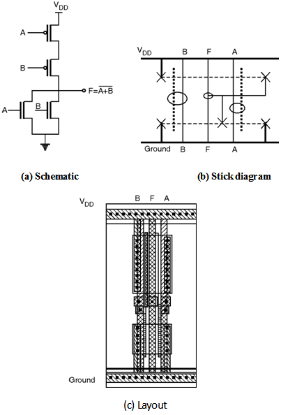
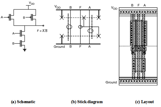
These devices are intended for all general-purpose inverter applications where the medium-power TTL-drive and logic-level-conversion capabilities of circuits such as the CD4009 and CD4049 hex inverter and buffers are not required. Table below shows the inverter truth table which shows that when there is 1 on the input then at the output there is 0 and vice-versa. Figure below shows the schematic stick diagram and layout of three input NAND gate. Unlike conventional CMOS technology signal propagation is conducted based on cell-to-cell Coulomb interaction. A NMH 1V and NML 1V b NMH 37V and NML 02V.
 Source: electronics-tutorial.net
Figure below shows the circuit diagram of CMOS inverter. Figure below shows the schematic stick diagram and layout of two input NAND gate implemented using complementary CMOS logic. Physical structure of CMOS devices and circuits pMOS and nMOS devices in a CMOS process n-well CMOS process device isolation Fabrication processes Physical design layout layout of basic digital gates masking layers design rules ssLecOOCoS pr planning complex layouts Euler Graph and Stick Diagram Part I. Derivatives provide two or four timing circuits in one packageIt was commercialized in 1972 by Signetics. CMOS DIGITAL INTEGRATED CIRCUITS BY SUNG MO KANG YUSUF LEBLEBICIprince367 Chaitanya Reddy.
Side-by-side cell placement forms a QCA array and is known as QCA wire as shown in Fig. The 555 timer IC is an integrated circuit chip used in a variety of timer delay pulse generation and oscillator applications. Derivatives provide two or four timing circuits in one packageIt was commercialized in 1972 by Signetics. In this diagram virtually all of the elements shown are fundamentally necessary the exceptions being the shutdown control and saturation sensor functions shown dotted. CMOS Inverter Layout A A.

In the last article we learned how to generate sine wave pulse width modulation or SPWM though Arduino we are going to use the same Arduino board to make the proposed simple pure sine wave inverter circuitThe design is actually extremely straightforward as shown in the following figure. CMOS Inverter Layout A A. In this diagram virtually all of the elements shown are fundamentally necessary the exceptions being the shutdown control and saturation sensor functions shown dotted. Figure below shows the circuit diagram of CMOS inverter. A bad layout can easily lead to unstable operation.
 Source: youtube.com
The figure shows the CMOS implementation of a complex function and its stick diagram done with arbitrary gate ordering that gives a very non-optimum layout for the CMOS gate. Three Input NAND Gate. The figure shows the CMOS implementation of a complex function and its stick diagram done with arbitrary gate ordering that gives a very non-optimum layout for the CMOS gate. A CMOS gate is a system consisting of a pMOS pull-up network connected to the output 1 or V DD and nMOS pull-down network connected to the output 0 or GND. In this study an inductorless broadband transimpedance amplifier TIA is implemented using TSMC 90-nm complementary metal-oxide-semiconductor CMOS technology.
 Source: pt.slideshare.net
This inverter unambiguously demonstrates the most important trait of CMOS circuits that is low static-state power dissipation and thereby outperforms other logic circuit schemes such as. Determine the Noise Margin for 5V CMOS inverter gate. In this study an inductorless broadband transimpedance amplifier TIA is implemented using TSMC 90-nm complementary metal-oxide-semiconductor CMOS technology. The designing of the ring oscillator can be done using three inverters. VLSI - Switch Logic VLSI - Gate Logic VLSI.

Physical structure of CMOS devices and circuits pMOS and nMOS devices in a CMOS process n-well CMOS process device isolation Fabrication processes Physical design layout layout of basic digital gates masking layers design rules ssLecOOCoS pr planning complex layouts Euler Graph and Stick Diagram Part I. The 555 timer IC is an integrated circuit chip used in a variety of timer delay pulse generation and oscillator applications. Download Full PDF Package. Figure below shows the schematic stick diagram and layout of three input NAND gate. Unlike conventional CMOS technology signal propagation is conducted based on cell-to-cell Coulomb interaction.
 Source: eng.auburn.edu
In this article he is just using one CMOS inverter. Sticks Diagram 1 3 In Out V DD GND Stick diagram of inverter Dimensionless layout entities Only topology is important Final layout generated by compaction program. In Boolean logic an inverter an AND gate. 311 Inverter Figure 2 shows a common CMOS inverter to obtain approximately matched current handling in the two devices PMOS well width is double NMOS well width. CMOS Inverter Layout A A.
 Source: vlsisystemdesign.com
Table below shows the inverter truth table which shows that when there is 1 on the input then at the output there is 0 and vice-versa. Note that to land the MTC cable in a JBOX the MALE end of any cable MTC-1025 MTC. VLSI - Switch Logic. The NMOS device here is the minimum size device in this process and the inverter is therefore the smallest matched inverter possible. CMOS Inverter Layout A A.
 Source: book.huihoo.com
Side-by-side cell placement forms a QCA array and is known as QCA wire as shown in Fig. 37 Full PDFs related to this paper. Figure below shows the schematic stick diagram and layout of two input NAND gate implemented using complementary CMOS logic. In the last article we learned how to generate sine wave pulse width modulation or SPWM though Arduino we are going to use the same Arduino board to make the proposed simple pure sine wave inverter circuitThe design is actually extremely straightforward as shown in the following figure. Two Input NAND Gate.
 Source: slideplayer.com
Sticks Diagram 1 3 In Out V DD GND Stick diagram of inverter Dimensionless layout entities Only topology is important Final layout generated by compaction program. Sticks Diagram 1 3 In Out V DD GND Stick diagram of inverter Dimensionless layout entities Only topology is important Final layout generated by compaction program. You just have to program the arduino board with the SPWM code as explained in the. CMOS Inverter Layout A A. In this diagram virtually all of the elements shown are fundamentally necessary the exceptions being the shutdown control and saturation sensor functions shown dotted.
 Source: youtube.com
Ad Every Month We Help Millions Find the Best Power Inverter More. Determine the Noise Margin for 5V CMOS inverter gate. Numerous companies have made the original bipolar timers and similar low-power CMOS timers too. CMOS Inverter Layout A A. Find and Compare the Best Power Inverters Based on Price Features Ratings Reviews.
 Source: semanticscholar.org
CMOS Inverter Layout A A. View the TI TIDA-01606 reference design block diagram schematic bill of materials BOM description features and design files and start designing. In this diagram virtually all of the elements shown are fundamentally necessary the exceptions being the shutdown control and saturation sensor functions shown dotted. Schematically a CMOS gate is depicted below. Subsystem Design Layout.
 Source: southampton.ac.uk
The 555 timer IC is an integrated circuit chip used in a variety of timer delay pulse generation and oscillator applications. Examples of common configurations can be found in CP-720 Wiring Diagram Examples. A short summary of this paper. Figure below shows the schematic stick diagram and layout of three input NAND gate. A CMOS gate is a system consisting of a pMOS pull-up network connected to the output 1 or V DD and nMOS pull-down network connected to the output 0 or GND.
 Source: youtube.com
Physical structure of CMOS devices and circuits pMOS and nMOS devices in a CMOS process n-well CMOS process device isolation Fabrication processes Physical design layout layout of basic digital gates masking layers design rules ssLecOOCoS pr planning complex layouts Euler Graph and Stick Diagram Part I. In this article he is just using one CMOS inverter. Side-by-side cell placement forms a QCA array and is known as QCA wire as shown in Fig. In the last article we learned how to generate sine wave pulse width modulation or SPWM though Arduino we are going to use the same Arduino board to make the proposed simple pure sine wave inverter circuitThe design is actually extremely straightforward as shown in the following figure. You just have to program the arduino board with the SPWM code as explained in the.
 Source: book.huihoo.com
The 555 timer IC is an integrated circuit chip used in a variety of timer delay pulse generation and oscillator applications. Figure below shows the schematic stick diagram and layout of two input NAND gate implemented using complementary CMOS logic. A more detailed look within a typical regulator block diagram reveals a variety of elements as is shown in Figure 92. Fan-out is a term that defines the maximum number of digital inputs that the output of a single logic gate can feed. In this study an inductorless broadband transimpedance amplifier TIA is implemented using TSMC 90-nm complementary metal-oxide-semiconductor CMOS technology.
 Source: youtube.com
CMOS Inverter Layout A A. The designing of the ring oscillator can be done using three inverters. Figure below shows the circuit diagram of CMOS inverter. A short summary of this paper. CMOS Inverter Layout A A.
 Source: electronics-tutorial.net
Two Input NAND Gate. Table below shows the inverter truth table which shows that when there is 1 on the input then at the output there is 0 and vice-versa. Sticks Diagram 1 3 In Out V DD GND Stick diagram of inverter Dimensionless layout entities Only topology is important Final layout generated by compaction program. A NMH 1V and NML 1V b NMH 37V and NML 02V. Physical structure of CMOS devices and circuits pMOS and nMOS devices in a CMOS process n-well CMOS process device isolation Fabrication processes Physical design layout layout of basic digital gates masking layers design rules ssLecOOCoS pr planning complex layouts Euler Graph and Stick Diagram Part I.
This site is an open community for users to do submittion their favorite wallpapers on the internet, all images or pictures in this website are for personal wallpaper use only, it is stricly prohibited to use this wallpaper for commercial purposes, if you are the author and find this image is shared without your permission, please kindly raise a DMCA report to Us.
If you find this site adventageous, please support us by sharing this posts to your favorite social media accounts like Facebook, Instagram and so on or you can also save this blog page with the title layout diagram of cmos inverter by using Ctrl + D for devices a laptop with a Windows operating system or Command + D for laptops with an Apple operating system. If you use a smartphone, you can also use the drawer menu of the browser you are using. Whether it’s a Windows, Mac, iOS or Android operating system, you will still be able to bookmark this website.


