Your Power supply schematic diagram images are ready in this website. Power supply schematic diagram are a topic that is being searched for and liked by netizens now. You can Download the Power supply schematic diagram files here. Download all royalty-free photos.
If you’re looking for power supply schematic diagram images information related to the power supply schematic diagram topic, you have visit the right blog. Our site frequently provides you with hints for seeing the maximum quality video and image content, please kindly surf and find more informative video articles and graphics that fit your interests.
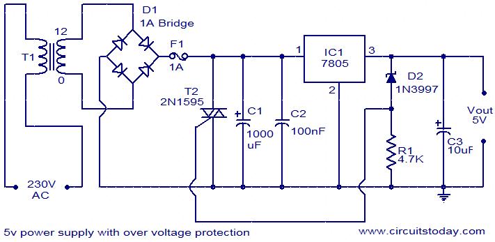
Power Supply Schematic Diagram. It consists of a compressor turbine and combustion chamber. The schematic symbol of the resistor are drawn in two different ways. This port can be used to power the device from the 5V supply and allows us to connect the board to the computer. For USB powering the KL26 interface processor has an on-board regulator that brings the external USB voltage into the correct range for the microbit board.
 Pin On De Cumpărat From pinterest.com
Connect the dynamic load to the output and set for the typical load current expected. Since the 7812 voltage regulator can handle only up to 1A of current the outboard transistor is used here. Sharp CX-68N5 SX-68N7 CRT TV schematics and circuit. Because It is high current normal parts a new circuit design. The above block diagram shows the flow of connections and the interconnections between the driver boards various. Connect the power supply to input.
This port can be used to power the device from the 5V supply and allows us to connect the board to the computer.
Sharp CX-68N57 Chassis GB-1 Schematic Diagramrar. For clarity the parts responsible for miscellaneous auxiliary functions such as current limit fan control and OV. The efficiency of this power supply ranges from 20 to 25. Here 225 K22uF 400 volts X rated capacitor is used to drop 230 volt AC. It consists of a compressor turbine and combustion chamber. RV Electrical Diagram Wiring Schematic.
 Source: pinterest.com
The function of the power supply is it converts energy from one form to another according to our requirement. December 14 2020 December 6 2020 by Aman Negi. To work as combustion plants with a conventional steam boiler. Modern designI used to show you the old circuit below. The efficiency of this power supply ranges from 20 to 25.
 Source: pinterest.com
A schematic diagram of a gas turbine power plant is shown in the figure. The above block diagram shows the flow of connections and the interconnections between the driver boards various. Regulated Power Supply Block Diagram. Power Supply Unit. Electronic Circuit Symbols for Power Supplies.
 Source: pinterest.com
The american style resistor is drawn as a zigzag resistor while the european style resistor is drawn as a rectangular resistor. For this we can use either DC power supply or USB connection as a source. Sharp CX-68N5 SX-68N7 CRT TV schematics and circuit. Power supply and power control circuit diagrams circuit schematics Note that all these links are external and we cannot provide support on the circuits or offer any guarantees to their accuracy. Connect the power supply to input.
 Source: pinterest.com
Because It is high current normal parts a new circuit design. In this article you will come up with the detail information about laptop schematic diagram. The function of the power supply is it converts energy from one form to another according to our requirement. A switched-mode power supply switching-mode power supply switch-mode power supply switched power supply SMPS or switcher is an electronic power supply that incorporates a switching regulator to convert electrical power efficiently. Schematic symbols for polarized and non-polarized capacitors Resistor.
 Source: pinterest.com
Modern designI used to show you the old circuit below. Here 225 K22uF 400 volts X rated capacitor is used to drop 230 volt AC. The diagram shown below is a simple transformer less power supply. Modern designI used to show you the old circuit below. To work as combustion plants with a conventional steam boiler.
 Source: pinterest.com
Resistor R2 is the bleeder resistor that remove the stored current from the capacitor when the circuit is unplugged. For clarity the parts responsible for miscellaneous auxiliary functions such as current limit fan control and OV. The flow of an electric current will be measured in terms of Watts. Sharp CX-68C4NZ Chassis 25A Schematic Diagramrar. It is used to drive the generators and supply peak loads in steam diesel or hydro plants.
 Source: pinterest.com
Regulated Power Supply Block Diagram. Hi Nasir You can try to use VFD or inverter to drive your submersible pumpThe inverter input power supply is single phase 240V and it will convert to 3 phase output to your motorBut please consider your Inverter current ampere rating same rated or higher than motor FLARule of thumb to sizing your inverter is FLA x 2 VFD current rating. To trace how the circuit works let us start with the 5V linear voltage regulator NCP1117ST50T3G. Using the same formula Amps50 50 x Volts120 these pedestals will supply 12000 Watts. Connect the dynamic load to the output and set for the typical load current expected.
 Source: ro.pinterest.com
The presentation of the interconnections between. A switched-mode power supply switching-mode power supply switch-mode power supply switched power supply SMPS or switcher is an electronic power supply that incorporates a switching regulator to convert electrical power efficiently. The main features of this power supply include the following. Why should make 0-30V variable Power Supply. Above are the parts needed to create a DC power supply.
 Source: pinterest.com
Full Bridge Unregulated Power Supply with Formulas. This port can be used to power the device from the 5V supply and allows us to connect the board to the computer. In this article you will come up with the detail information about laptop schematic diagram. To trace how the circuit works let us start with the 5V linear voltage regulator NCP1117ST50T3G. The magnetic materials used in this power supply are CRGO core or Stalloy.
 Source: pinterest.com
Although steam power station simply involves the conversion of the heat of coal combustion into electrical energy yet it embraces many arrangements for proper working and efficiencyThe schematic diagram of steam power station is shown in the figure belowThe whole arrangement can be divided into the following stages for the sake of simplicity. This regulator has a pretty straightforward function. For this we can use either DC power supply or USB connection as a source. This port can be used to power the device from the 5V supply and allows us to connect the board to the computer. Some circuits would be illegal to operate in most countries and others are dangerous to construct and should not be attempted by the inexperienced.
 Source: br.pinterest.com
The output from an ordinary power supply is fed to the voltage regulating device that provides the final output. Without R2 there is chance for fatal shock if the circuit is touched. Using the same formula Amps50 50 x Volts120 these pedestals will supply 12000 Watts. The USB the battery connector and the 3V pad on the edge connector. Above are the parts needed to create a DC power supply.
 Source: in.pinterest.com
This port can be used to power the device from the 5V supply and allows us to connect the board to the computer. The function of the power supply is it converts energy from one form to another according to our requirement. Power Supply Unit. Turn on the DC power supply and adjust again as needed for nominal voltage at the input terminals. December 14 2020 December 6 2020 by Aman Negi.
 Source: pinterest.com
Schematic symbols for polarized and non-polarized capacitors Resistor. Like other power supplies an SMPS transfers power from a DC or AC source often mains power see AC adapter to DC loads such as a personal computer while. It is used to drive the generators and supply peak loads in steam diesel or hydro plants. Hi Nasir You can try to use VFD or inverter to drive your submersible pumpThe inverter input power supply is single phase 240V and it will convert to 3 phase output to your motorBut please consider your Inverter current ampere rating same rated or higher than motor FLARule of thumb to sizing your inverter is FLA x 2 VFD current rating. The USB the battery connector and the 3V pad on the edge connector.
 Source: in.pinterest.com
Sharp CX-68LF58 Chassis NFC Schematic Diagramrar. To supply mechanical drive for auxiliaries. The center tapped secondary coil should be rated about 15V to 18V at 1 A or higher. For USB powering the KL26 interface processor has an on-board regulator that brings the external USB voltage into the correct range for the microbit board. Power to the microbit can be provided by 3 sources.
 Source: in.pinterest.com
Below is the schematic for the DC power supply so that we can see how all the parts are connected and are brought together. Sharp CX-68N5 SX-68N7 CRT TV schematics and circuit. A switched-mode power supply switching-mode power supply switch-mode power supply switched power supply SMPS or switcher is an electronic power supply that incorporates a switching regulator to convert electrical power efficiently. Sharp CX-68C4NZ Chassis 25A Schematic Diagramrar. The program is uploaded to the board serially from the computer through the USB cable.
 Source: pinterest.com
Hi Nasir You can try to use VFD or inverter to drive your submersible pumpThe inverter input power supply is single phase 240V and it will convert to 3 phase output to your motorBut please consider your Inverter current ampere rating same rated or higher than motor FLARule of thumb to sizing your inverter is FLA x 2 VFD current rating. A regulated power supply essentially consists of an ordinary power supply and a voltage regulating device as illustrated in the figure. The USB the battery connector and the 3V pad on the edge connector. Arduino Mega Pinout Pin diagram Schematic and specifications in detail. Connect the power supply to input.
 Source: pinterest.com
Full Bridge Unregulated Power Supply with Formulas. To work as combustion plants with a conventional steam boiler. Due to its four-prong receptacle the 50-amp socket provides significantly more power. For this we can use either DC power supply or USB connection as a source. The schematic symbol of the resistor are drawn in two different ways.
 Source: pinterest.com
Sharp CX-68N57 Chassis GB-1 Schematic Diagramrar. The program is uploaded to the board serially from the computer through the USB cable. The diagram shown below is a simple transformer less power supply. Using the same formula Amps50 50 x Volts120 these pedestals will supply 12000 Watts. Resistor R2 is the bleeder resistor that remove the stored current from the capacitor when the circuit is unplugged.
This site is an open community for users to share their favorite wallpapers on the internet, all images or pictures in this website are for personal wallpaper use only, it is stricly prohibited to use this wallpaper for commercial purposes, if you are the author and find this image is shared without your permission, please kindly raise a DMCA report to Us.
If you find this site helpful, please support us by sharing this posts to your preference social media accounts like Facebook, Instagram and so on or you can also bookmark this blog page with the title power supply schematic diagram by using Ctrl + D for devices a laptop with a Windows operating system or Command + D for laptops with an Apple operating system. If you use a smartphone, you can also use the drawer menu of the browser you are using. Whether it’s a Windows, Mac, iOS or Android operating system, you will still be able to bookmark this website.


